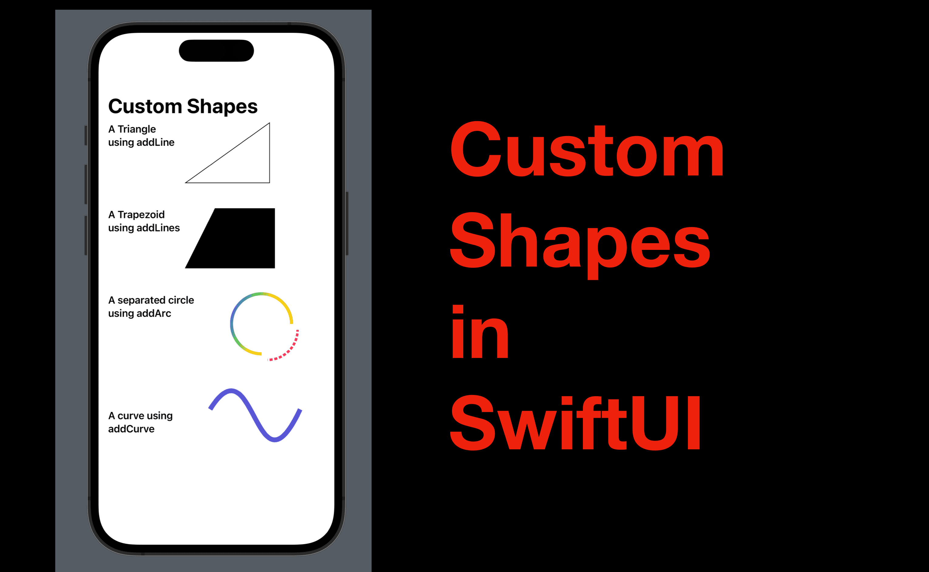
Custom Shapes in SwiftUI
Hi everyone! In the post yesterday, we covered the standard SwiftUI shapes - rectangle, rounded rectangle, circle, ellipse, and capsule and discussed how to style these shapes with view modifiers. Apartment from these shapes, there’s one more Shape structure in SwiftUI called Path, which can be used to create custom shapes for more interesting user interfaces. Today, we’ll going to take a look at how to use Path in SwiftUI.
The code in this post is available here.
Overview
What is Path? Path is a public struct in SwiftUI for custom 2D shape creation. There’re multiple ways to create a Path and for this post, we’ll focus on a commonly used initializer: init(_ callback: (inout Path) -> ()).
The inout keyword makes the Path mutable in the closure, therefore in a SwiftUI view, we can use the pattern below to create a path.
Path { path in
    //define or configure the path here
}
Coordinate in iOS
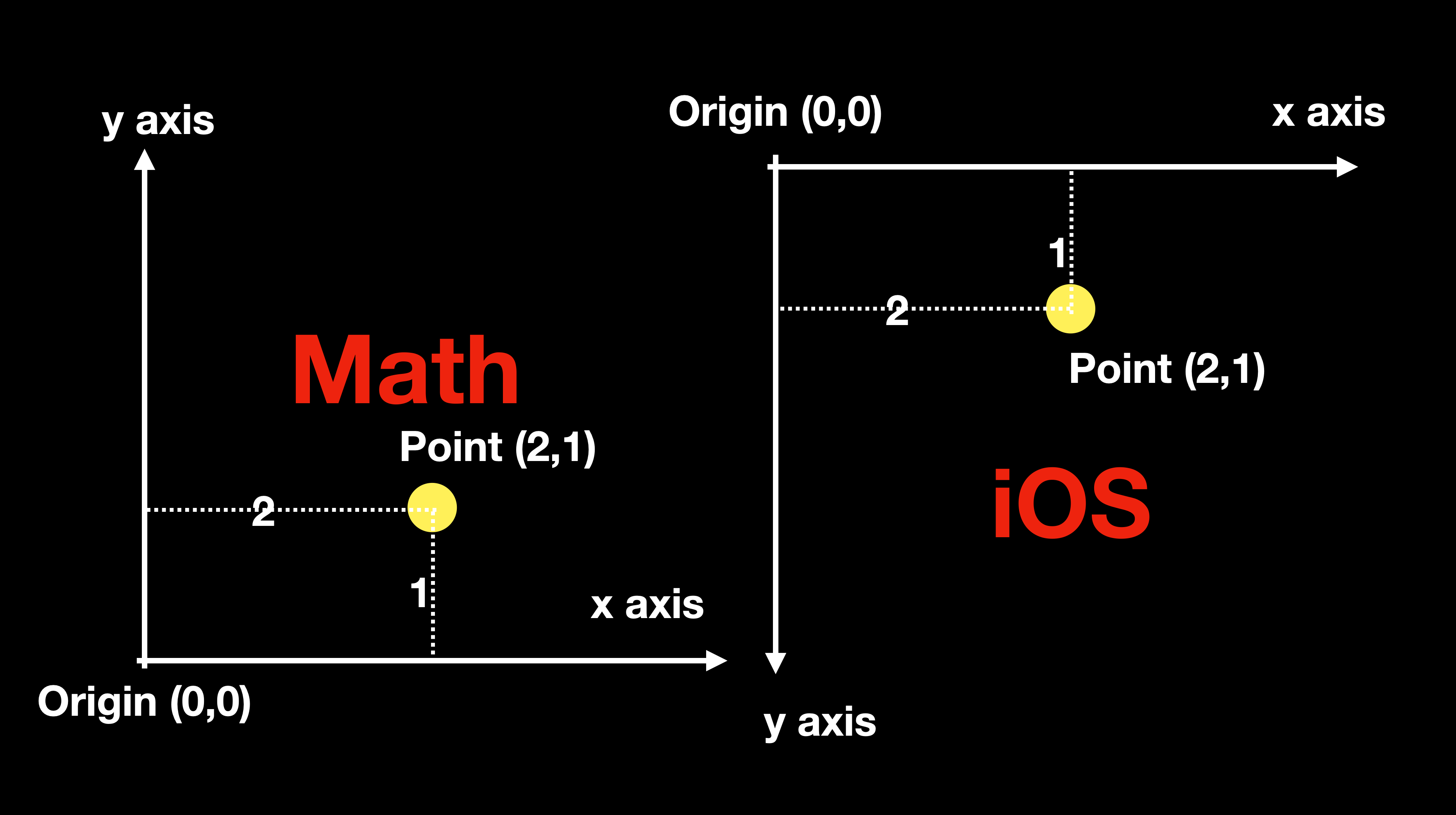
Before getting started, it’s necessary to take a look at the coordinate system in iOS. Below is a comparison of the mathematical coordinate and the one in iOS. The biggest difference is that the point of origin (0,0) is located at the upper left corner of a screen (or a frame), and going downward will increase the value on the y-axis.
In Swift, the location of a point can be represented by CGPoint with its x and y values. For instance, point (2,1) can be written as CGPoint(x: 2, y: 1). Note that both of the x and y values are CGFloat type instead of a double or integer.
Path basically means the path of movement of a point. And a shape can be composed of one or multiple paths.
Now we’re ready to move forward. So let’s take a look at how to create shapes with functions in Path.
move and addLine
The function move(to: CGPoint) is often used to define the starting point of a shape, by going to the point to to start drawing. And addLine(to: CGPoint) connects the currently moved-to point and the to point and forms a straight line.
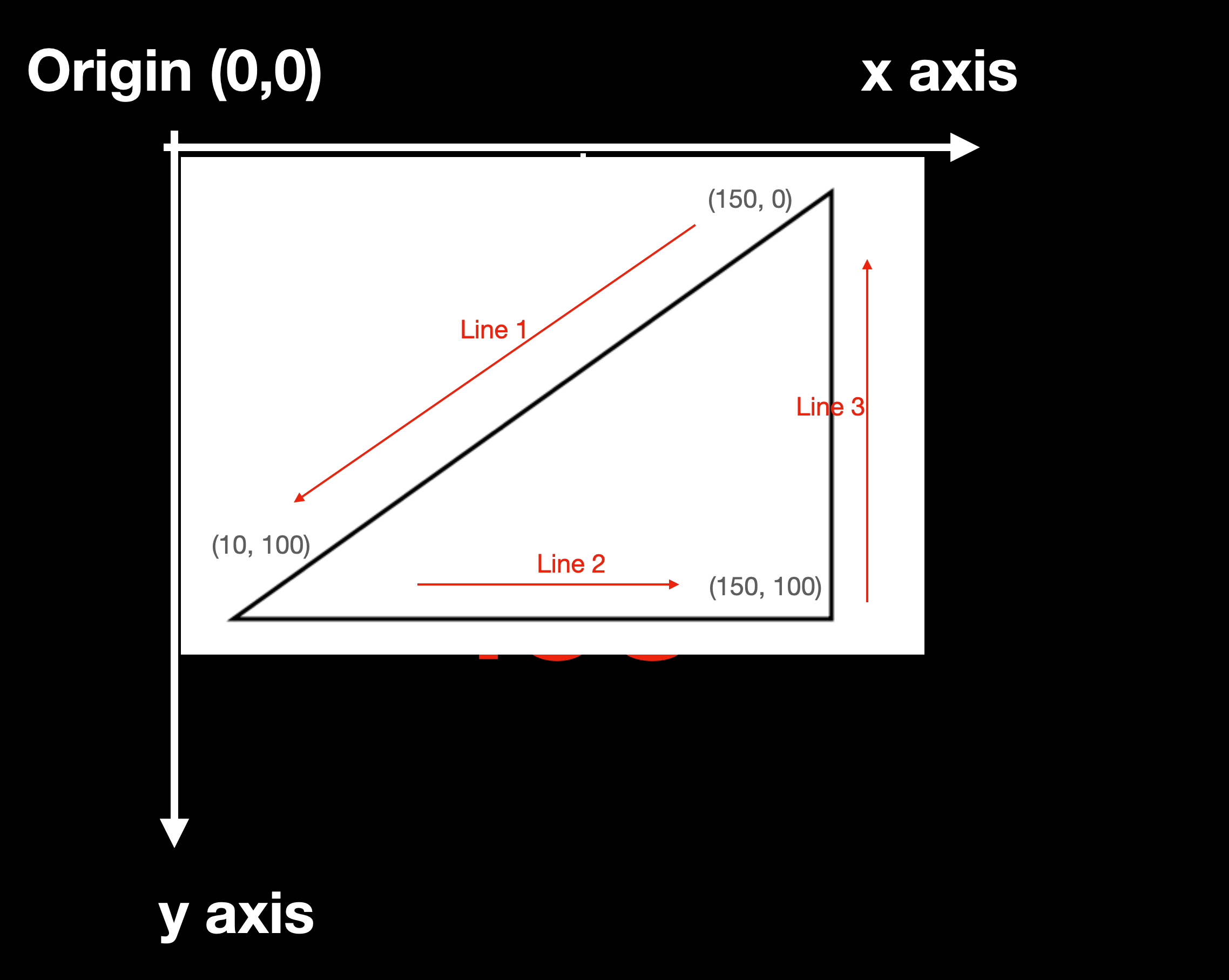
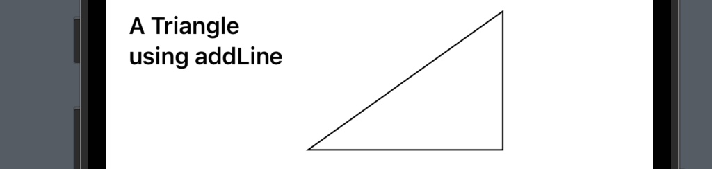
Let’s look at the example below, where a triangle is drawn.
Path { path in
    path.move(to: CGPoint(x: 150, y: 0))
    path.addLine(to: CGPoint(x: 10, y: 100))
    path.addLine(to: CGPoint(x: 150, y: 100))
    path.addLine(to: CGPoint(x: 150, y: 0))
    // or path.closeSubpath() //for the last line closing the shape
}
.stroke()
The .move function set the starting point at (150, 0). And the three addLine functions added three straight lines, as shown in a coordinate below. And finally, the stroke modifier made the shape bordered with no fill color.
addLines
It might be easy to right addLine function to create a shape like a triangle, since there are only three lines required. What if we need a trapezoid?
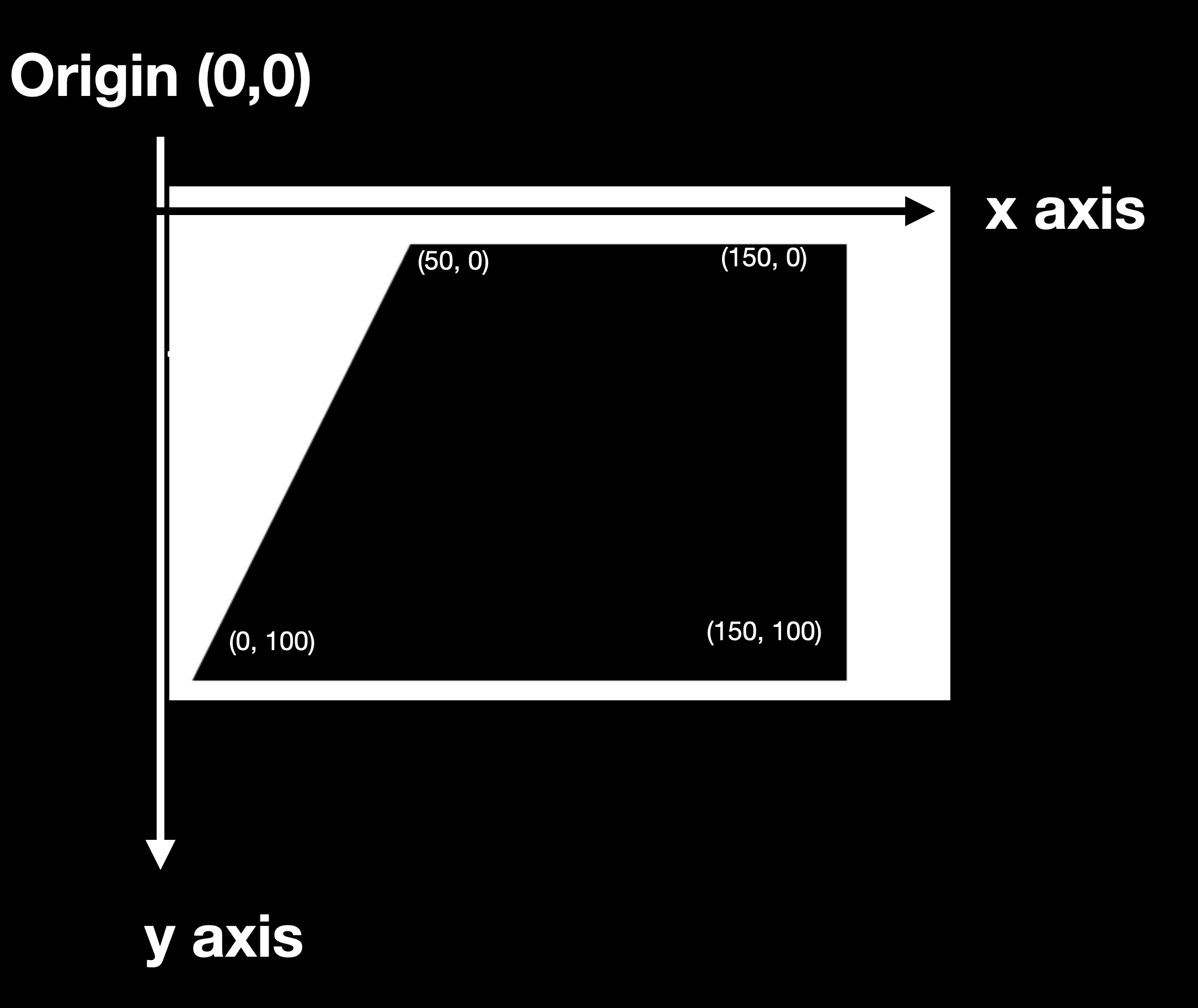
In such a case, we can use the function addLines and pass in an array of CGPoints, including the starting point.
Path { path in
    path.addLines([
        .init(x: 50, y: 0),
        .init(x: 150, y: 0),
        .init(x: 150, y: 100),
        .init(x: 0, y: 100)
    ])
}
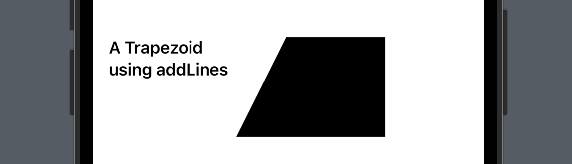
The coordinate below shows the position of these points. And the screenshot after it shows how the shape looks like in the preview canvas.
addArc
Now let’s see how to create an arc shape. Before looking into the code, I’d like to introduce the angle and degrees in iOS too. (Also applicable to some other languages.)
The clockwise direction is the opposite direction of the natural clockwise direction;
0-degree starts from the right hand side (basically the x-axis).

Now let’s take a look at the code below. It declared a path and called the addArc function. This function requires the following parameters:
center: CGPoint -> to determine the location of the arc
radius: CGFloat -> to determine the size of the arc
start angle: Angle
end angle: Angle
clockwise: Bool
The last three parameters might be tricky as the value might not represent in a natural way. So in a mathematical language, the arc created by this code snippet starts at 90 degrees and ends at 270 degrees, and the shape is drawn in the counterclockwise direction.
Then the modifiers applied made it a stroke, with a linear gradient fill color.
Path { path in
    path.addArc(center: .init(x: 100, y: 50), radius: 50, startAngle: .init(degrees: 0), endAngle: .init(degrees: 90), clockwise: true)
}
.stroke(lineWidth: 5)
.fill(LinearGradient(colors: [.indigo, .indigo, .indigo, .green, .yellow], startPoint: .topLeading, endPoint: .bottom))

addCurve
Finally, let’s look at the addCurve function. To create a curve, we also need to specify a starting point, so this function is often used together with move(to: CGPoint).
The addCurve have three parameters:
to: CGPoint -> the ending point of the curve
control1: CGPoint
control2: CGPoint
Both of the controls are CGPoints, and they are used to control the direction of the curve path (the controls are also called apex points).
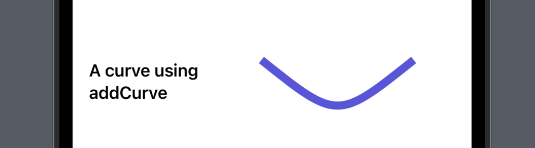
Let’s take a look at the code below. This block of code creates a path with a downward curve. Since the controlling points are the same, the curve looks symmetric. (as the x value 125 is in the middle, (50 + 200) / 2 = 250.)
Path { path in
    path.move(to: .init(x: 50, y: 0))
    path.addCurve(to: .init(x: 200, y: 00), control1: .init(x: 125, y: 60), control2: .init(x: 125, y: 60))
}
.stroke(lineWidth: 8)
.foregroundColor(.indigo)
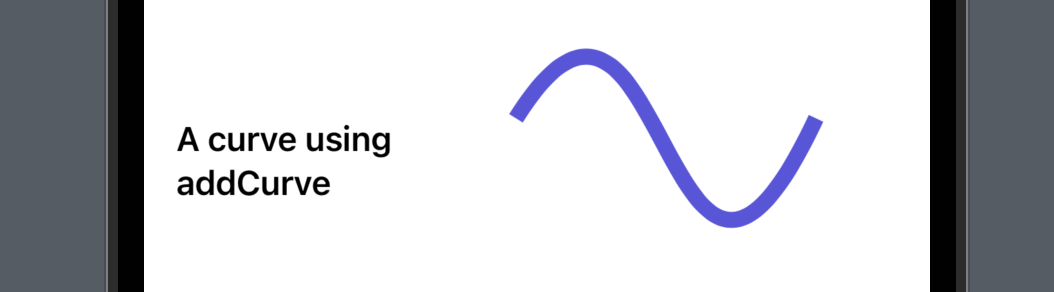
If you change the controlling point’s value you can find that the curve will move toward to the point with a higher absolute x or y value, and the negative/positive symbol determines the direction.
        Path { path in
            path.move(to: .init(x: 50, y: 0))
            path.addCurve(to: .init(x: 200, y: 00), control1: .init(x: 125, y: -120), control2: .init(x: 125, y: 160))
        }
        .stroke(lineWidth: 8)
        .foregroundColor(.indigo)
For instance, if we change the first controlling point to (125, -120), the left side of the curve will move upward.
That’s all for the custom shapes. I hope you learned something and will be able to create various of desired shapes in your project.
If you find this post helpful, please hit the like button or leave a comment. Also remember to subscribe to my newsletter if you’d like to receive more posts like this via email.
I’ll see you all in the next post!